Sonargraph’s domain specific language (DSL) to describe architecture aspects is very powerful. An architecture aspect consists at least of 1 top-level architecture file that has been added to the architecture configuration and is checked automatically. Such a top-level architecture file can include other architecture files reusing common definitions. For any checked architecture file (i.e. an aspect) it is possible to generate a UML component diagram.
A UML component diagram complements in several ways our text based architecture aspects:
-
It is a commonly accepted form of communicating architecture definitions.
-
It shows the resulting architecture aspect in 1 diagram even if it is spread over several files.
-
It can be used to cross-check the underlying text based architecture aspect (i.e. are the resulting restrictions the intended ones?).
Let’s have a look at a concrete example. Suppose we want an architecture aspect containing 2 (vertical) slices (domain driven divisions) Customer and Common and 3 layers (technical divisions) View, Model and Persistence. Furthermore we want a separate License component usable only from the Common slice and a JDBC component usable only from the Persistence layers.
One way to express this with our architecture DSL would be the following:
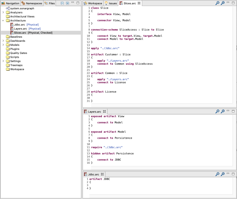
Our top-level architecture file would be Slices.arc, using Layers.arc and Jdbc.arc. Make sure to add the top-level architecture file to the architecture check via the context menu entry Add To Architecture Check on the corresponding file. As you can see above the Slices.arc is checked. Note that in the example above we have omitted all include patterns that would be needed to match the code for the sake of simplicity.
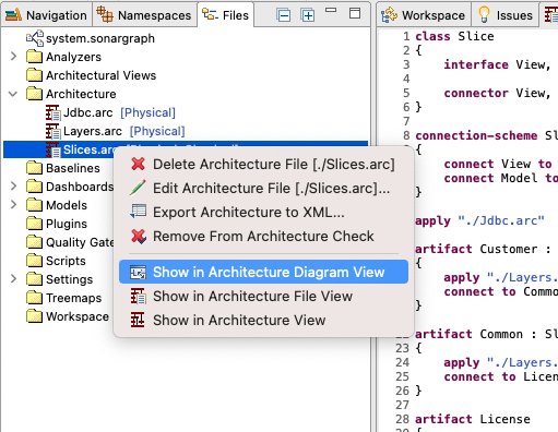
Once we have a checked architecture file we can simply generate an UML component diagram via the context menu entry Show in Architecture Diagram View on the corresponding file.
In our example that results in the following UML component diagram:
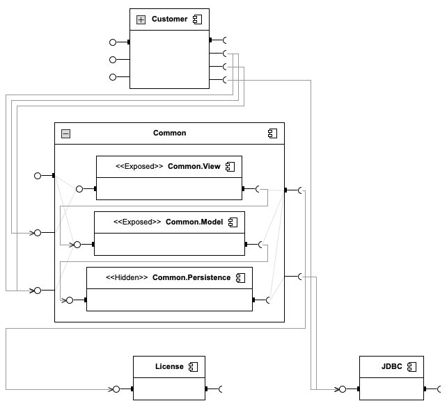
The generated UML component diagram is interactive in the sense that you can select different elements (e.g. components, connectors, interfaces). The selected element is highlighted in yellow along with it’s connected elements (e.g. a connector that is included in a higher level connector), reachable (i.e. allowed) elements are highlighted in green. Components also might have child components, such components can be expanded and collapsed (e.g. Customer and Common).
Connectors and interfaces that show a small solid black rectangle on their anchor point are directly defined by their component. The ones without that decorator are coming from child components.
The different elements also offer a tooltip showing interesting information about incoming/outgoing connections and other aspects. Clicking into the tooltip window will leave it open (until pressing ESC). The content of the tooltip may be selected and copied.
The currently visible UML diagram may be exported as an image using the context menu.
The components are layout in a levelized grid. Components with no incoming connections are on top, components with no outgoing connections are on the bottom. The further down a component is, the more other components depend on it. Components on the same level have more incoming dependencies from left to right. Components with the same number of incoming dependencies have more outgoing dependencies from left to right.
As long as the view stays open it is also updated when saving changes to the underlying architecture file(s).
Lets cross-check the usage of our JDBC component by selecting it:
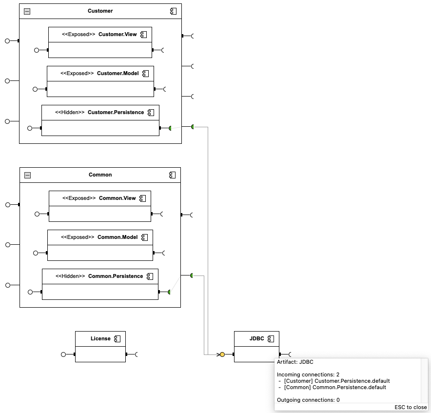
As we can see JDBC may only be used from the Persistence layers. More details are provided by the tooltip of the component.
Let’s check our License component:
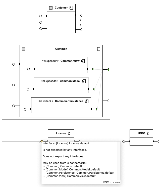
Great, our License component may only be used from the Common slice. Again, more information is provided by the tooltip of the interface.
