The Cycle Breakup view can be opened via the context menu of the Cycle view. The context menu must be requested without a selection (i.e. right click on the background).
Pressing "Compute" calculates a breakup set of edges to completely remove the given cycle. The algorithm used was presented in 'Combinatorial Algorithms for Feedback Problems in Directed Graphs' written by Camil Demetrescu and Irene Finocchi. The authors summarize the algorithm as follows:
Roughly speaking, our algorithm tries to find a compromise between two (somewhat opposite) approaches, i.e., removing light arcs, that is, arcs with small weight, and removing arcs belonging to a large number of cycles. Indeed, light arcs are convenient to be deleted as they contribute to breaking cycles, yet increasing the weight of the feedback set only to a limited extent. On the other hand, if a heavy arc belongs to a large number of cycles, it may be convenient to choose it instead of a numerous set of light arcs.
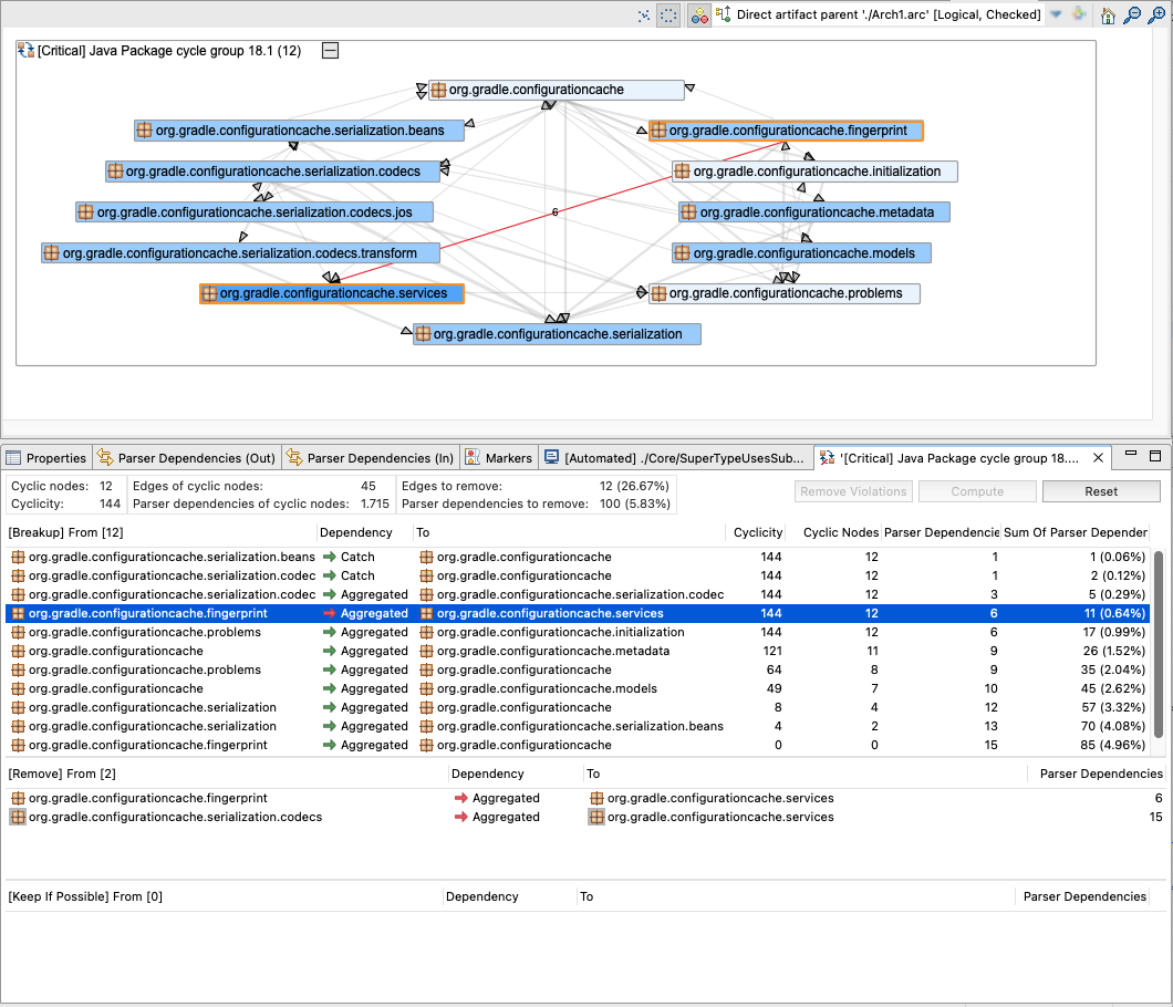
The "Breakup" table shows edges from top to bottom representing the removal order and the effect on cyclicity and number of cyclic nodes.
Dragging edges to the "Remove" table instructs the algorithm that these should be explicitly removed without considering the number of parser dependencies. Drag them back to the "Breakup" table to remove this configuration. Edges to be explicitly removed can also be dragged from the corresponding cycle view into the "Remove" table. If more edges are contained in the "Remove" table than are necessary to break up the cycle, the breakup set is over-defined. Those unnecessary edges are indicated by a grey background of the 'from' and 'to' element.
Pressing "Remove Violations" moves all violating edges to the "Remove" table.
Dragging edges to the "Keep If Possible" table instructs the algorithm that these should be kept if possible. If no more edges are left to remove even those that should be kept are considered. Drag them back to the "Breakup" table to remove this configuration. If the algorithm needs to consider edges as removal candidates that should be kept, the edges are analyzed from bottom to top (i.e. the topmost edge is the last to be considered). This order can be changed in the "Keep If Possible" table by dragging edges up or down. Edges that should be kept but need to be removed are highlighted in both tables with a yellow background of the 'from' and 'to' element.
Changing the set of edges to be explicitly removed or kept requires a re-computation. This is indicated by a grey background color in the "Breakup" table and an (again) enabled "Compute" button.
If the "Breakup" table contains the correct edges that should be removed, a "delete" refactoring can be defined by multi-selecting the entries and open the context menu via right mouse click. For details, see Section 10.1, “Creating Delete Refactorings ”
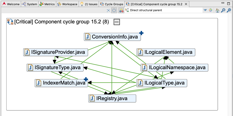
Highlighting Added Cyclic Elements
If a baseline has been created and activated (see Chapter 14, Examining Changes) added cyclic elements are highlighted in the Cycle view with a blue plus sign as shown in the screenshot below. These elements and their incoming/outgoing dependencies are usually a good starting point for refactorings.