Sonargraph allows the definition of an architecture via a Domain Specific Language (DSL) that is expressive and readable enough so that every developer is able to understand it. The graphical representation in Sonargraph 7 allowed the creation of the architectural blueprint in one single diagram. This led to potentially very big and complex diagrams that are difficult to understand.
The requirements for the new DSL approach were the following:
-
It should be possible to describe an architecture in a set of files. Some of them should be generic enough so that they could be reused by many projects, e.g. a generic template describing the layering of a system.
-
It should be possible to describe an architecture in form of several completely independent aspects. E.g. one aspect describes layering, another aspect describes components and a third aspect looks at separation of client and server logic.
-
On the other hand the language should also be powerful to describe the complete architecture in a single file.
-
The DSL must be easy to read and easy to learn.
-
The restrictions for dependencies should allow also the specification of dependency types (e.g. "new", "inheritance", etc.).
To create an architecture description you select "New Architecture File..." from the menu "File/New...". That will open an editor where you can work on your architecture description. You can have as many architecture files as you like. If the description should be used to check for architecture violations, the architecture file needs to be added to Sonargraph's architecture check. This is done in the "Files" tab of the "Navigation" view by right-clicking on your architecture file and select "Add to Architecture Check..." from the context menu. If you later decide to remove the file from Sonargraph's architecture check you can also do this via the context menu.
It is also recommended to open the "Architecture View" while working on an architectural model via the menu → → . The view is split vertically into two main sections. In the top section there are three tabs to provide a quick overview about the checked files in the physical and logical model as well as which files are currently not part of the architecture check. These unchecked files might also include files that are imported by currently checked architectural files.
TIP
The context menu of a selected architecture model or artifact in the Architecture view offers the option to show the selection in the Exploration. This usually reveals very quickly where the architecture needs adjustment or where violations exist.
TIP
The context menu of a selected (and checked) architecture model also offers the option to show it as an UML Component diagram in an Architecture Diagram view (See Chapter 12, Visualizing Architecture Aspects for details).
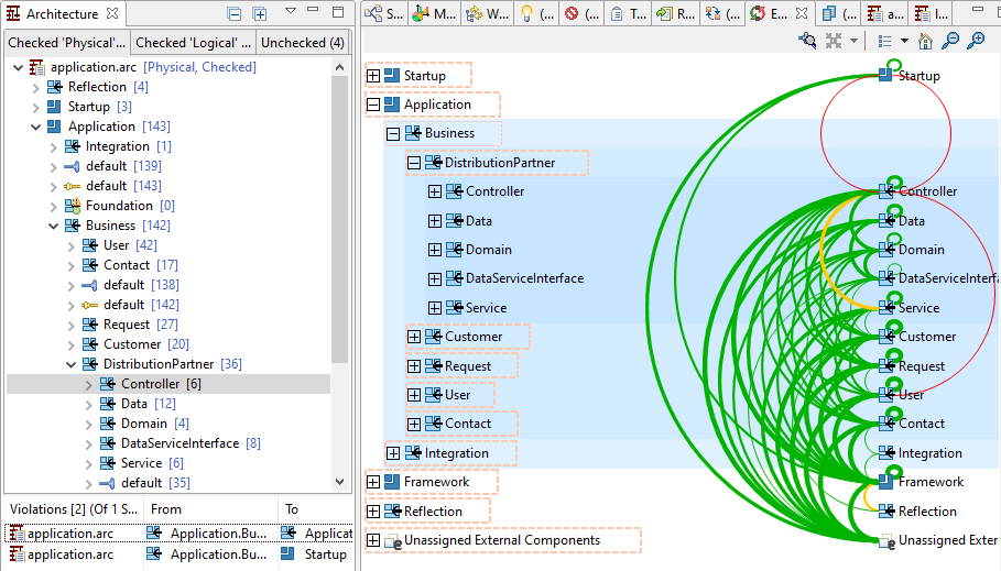
The tabs for logical and physical models contain architecture models that are actively checked. That means you will be able to see which elements are assigned to which artifact by browsing through the tree. You can also easily see which elements have not been assigned to any artifact by inspecting the nodes for "Unassigned internal/external components".
The bottom section lists all architecture violations of the element selected in the middle section. If no element is selected all architecture violations from all models are shown. If you click on a line in that table the associated violating dependencies are shown in the "Parser Dependencies Out" auxiliary view.
