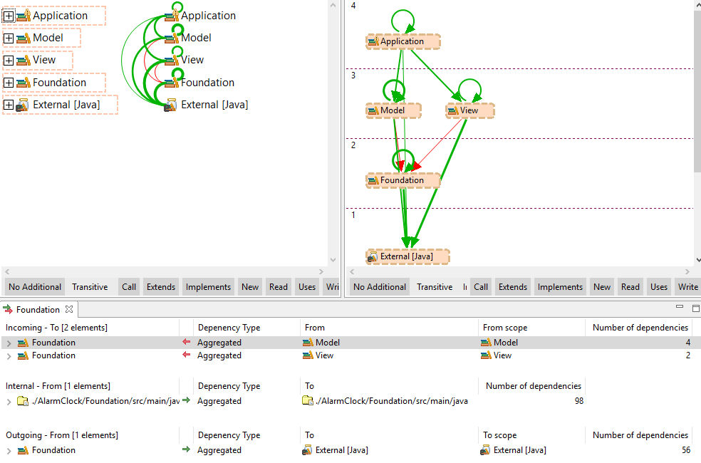
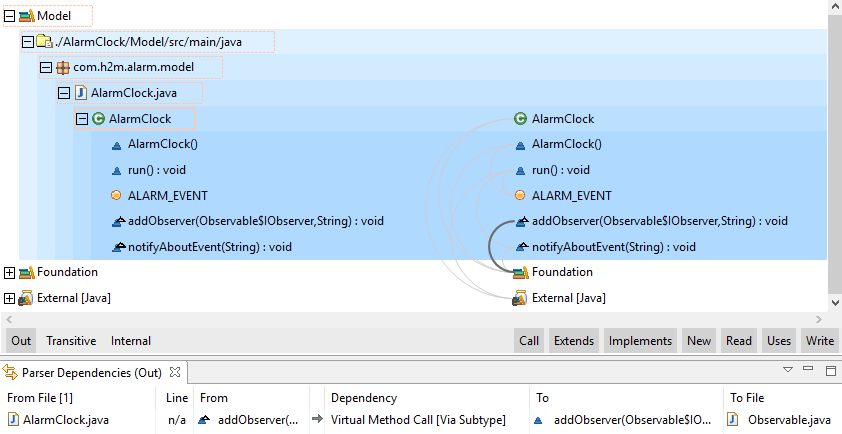
For Graph and Workspace dependencies view, the focus concept is the key element to understand how these views are created and how they can be modified to make a deeper analysis of the dependencies between elements. Any of these views (except for the Workspace Dependencies view when there are not workspace elements in the system) will have at least one element in focus and any number of elements not in focus.
-
Elements in Focus: Elements that are the center of the analysis. Dependencies will be calculated for these elements according to the selected focus mode. When a Graph view for example is requested by the user for a set of selected elements, these elements will be the ones in focus.
-
Elements not in Focus: Elements that appear as a result of the calculation of the dependencies for the elements in focus. They appear in the views because they are the endpoint of a dependency from or to an element in focus but they are not the active part of the dependency analysis.
Focus Modes
When creating a new Graph or Workspace Dependencies view or using the focus operation inside them, one of the following focus modes can be selected:
-
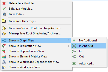
No Additional Dependencies
 : Only the selected elements and the dependencies between them are going to be part of the displayed content.
-
Incoming Dependencies
 : The selected elements plus the elements that directly depend on them will be part of the displayed content
along with the
dependencies between all of them.
-
Outgoing Dependencies
 : The selected elements plus the elements which they depend on will be part of the displayed content along
with the
dependencies between all of them.
-
Incoming and Outgoing Dependencies
 : The selected elements plus the elements which they depend on and the elements that directly depend on
them will be part of
the displayed content along with all the dependencies involved.
Transitive Dependencies
Sometimes it is required to analyze relationships between elements beyond the direct dependencies. For this reason, Sonargraph offers the option of taking into account the transitive dependencies for the focus operations. To better understand this concept assume a system with the following dependencies between elements A, B, C, D and X:
-
Element A depends on element B: A -> B
-
Element B depends on element X: B -> X
-
Element X depends on element C: X -> C
-
Element C depends on element D: C -> D
Taking element X as a reference for this example, we can express the relationship between A and X as A -> B -> X and the relationship between X and D as X -> C -> D. For these relationships the following statements are true:
-
X has a transitive incoming dependency from A
-
X has a direct incoming dependency from B
-
X has a direct outgoing dependency to C
-
X has a transitive outgoing dependency to D
Graph-Based Views Properties
Besides the input elements and the focus mode the Graph-based views need the following 3 properties to be created:
-
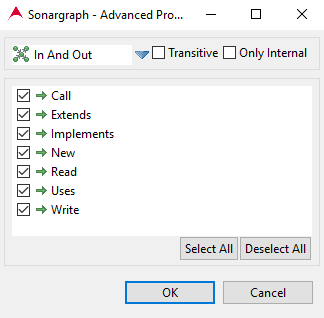
Transitivity: Users must indicate whether they want to see transitive dependencies for the supplied input or not. See Section 8.11.2.1, “Transitive Dependencies”
-
Only Internal: If selected, all elements under the External node will be excluded from the view.
-
Dependency types: Users might want to focus the analysis on certain types of dependencies. The lower section in the dialog allows the selection of the dependency types that will be considered for view creation or focus operations.
Quick View Creation
Graph-based views can be created by right clicking on a selection of elements, selecting the view to open and providing one of the four focus modes from the context menu.
A new view will be created with the supplied focus parameter, only direct dependencies (not transitive), both internal and external elements and all the parser dependency types available.
Advanced View Creation
If more configuration options are need upon view creation, users can right click on a selection, select the view to open and click on 'Advanced...'. That will open the Advanced View Creation dialog where all available options can be configured.
The dialog shown in the previous image shows the advanced representation creation dialog where focus mode, properties and dependency types can be specified prior to creation. See: Section 8.11.2.1, “Focus Modes”, Section 8.11.2.1, “Graph-Based Views Properties”
Applying Focus
Since Graph-based views can display an overwhelming amount of information, it is possible to perform focus operations on these views in order to reduce the amount of displayed information to a set of nodes and edges that the user wants to focus his attention on. Focus operations are performed by using the focus toolbar.
Focus Properties
The focus operation requires the combination of the Graph-based properties (See Section 8.11.2.1, “Graph-Based Views Properties”) and the following properties of its own:
-
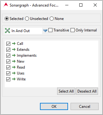
Selection: Users can focus a view using the selected or unselected elements. It is also possible not to use a selection, in which case, only the dependency types will be modified.
-
Only Visible
 : If selected, only nodes and edges visible at the time of the focus operation will be considered, otherwise,
all the model
will be used for the focus operation.
Quick Focus
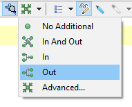
The focus button in the focus toolbar offers a dropdown menu with 4 options to perform a quick focus operation.
As the image shows, there is one menu entry for each focus mode. These menu entries can be used to perform quick focus operations which will use the current selection, the current value of the 'Only Visible' button, the focus mode of the menu entry and keeps all the other properties of the current view (dependency types, only internal and transitive).
Advanced Focus
If more configuration is needed to perform a focus operation, users can push directly the focus button in the focus toolbar or use the 'Advanced..' menu entry in the dropdown menu of this same button. Any of these operations will open the 'Advanced Focus' dialog which allows the configuration of all view and focus properties.
Architecture and Colors
When the used license contains the Architecture feature, the Exploration, Graph, Cycle and Dependencies views will use a set of colors to show whether the edges (or dependencies in the case of the Dependencies view) contain architecture violations or not.
-
Green Color: All underlying dependencies comply with the architecture.
-
Yellow Color: At least one but not all of the underlying dependencies create architecture violations.
-
Red Color: All underlying dependencies create architecture violations.
Besides these 3 colors, views can eventually show some dependencies that will always be grayed. This means that these dependencies are not taken into account by the architecture check, thus they are neither allowed nor violating dependencies.
Selection and Colors
In the case of the Exploration Graph view the selection will cause edges to display or hide their architecture-related color. If a node is selected, its incoming and outgoing edges will reveal their architecture-related color, all other edges will be grayed. If an edge is selected, it will be the only one revealing its architecture related color and the rest of them will be grayed. This is of course assuming that a license containing the Sonargraph Architecture feature is installed, otherwise, incoming and outgoing edges of selected nodes as well as selected edges will have a darker gray color whereas all other edges will have a lighter gray color. This is also the case for Workspace Dependencies and Include Dependencies views, where edges will always be presented in gray-scale colors.
